Marine Grounding Systems
In contrast to aluminium or steel hulls, on fibreglass hulls, the different metal-based
underwater components such as thru-hull fittings, keel, engine, propeller, rudder and shafts
are not electrically connected through the hull's conductivity.
Given this, some special attention must be paid on fibreglass hull vessels to obtain a functional
electrical grounding system.
At first glance making a grounding system on a floating vessel seems a simple thing since the
surrounding seawater provides a good ground, and it is just an issue of connecting all
the submerged metal parts together to a common electrical ground.
However, things are considerably more complicated, because in addition to the AC ground,
also a DC ground or return line, a lightning ground, and a RF ground plane for the radio
systems must be considered.
The first thought, to simply make the ground connection to the metal thru-hulls, propeller
shaft or other underwater metal, unfortunately, can and probably will, give rise to serious
electrolytic corrosion problems.
AC-Ground
If a isolator transformer for the AC power is used, an explicit AC ground can be omitted.
Otherwise, the AC ground for each power socket should be wired to a common point that is
connected to shore ground using a galvanic isolator.
For the seawater connection, only one single point of contact should be made.
For this purpose, the engine block may be a favourable point of contact.
DC-Ground
If each 12-V DC load has its individual feed and return path, the need for an explicit DC ground
can be avoided.
It is clear that the wire size of the complete electrical path shall be chosen according to the
required current rating (including surging) of the load.
The electrical path for each DC application (lights, fans, ..)
will start at the 12-V circuit breaker board, will then go to the load and
will return to the negative DC power bus that is connected with a single wire
large enough to withstand the expected total battery current to the
negative pole of the battery.
To avoid DC-load inducted corrosion, no DC-load current should be routed
through any of the metal parts such at mast, life lines, keel bolts, etc.
Always provide an appropriate DC return path to the negative bus from each 12-V load.
Lightning Ground
For good lightning protection, the mast and the rigging should be directly electrically connected
to the seawater.
The required wiring should be short without bends and rated for very high currents.
This can best be obtained by connecting a couple of 4 AWG (5-mm diameter) battery cables from
the base of the metal mast to the nearest keel bolts of the external ballast.
For an internal ballast, a lightning ground plate should be installed.
One square foot is recommended for use in salt water; fresh water requires much more.
Thru-hulls or a sintered bronze radio ground (e.g. Dynaplate) are unreliable for use as a
lightning ground.
For additional safety, a series of 6 AWG (4-mm diameter) wires can be installed to connect
the upper shroud chainplates and the headstay chainplate to the keel bolts or ground plate.
Each of the cables that is used for lightning ground wires must be led as directly as
possible, with any necessary bends being smooth and gradual.
If feasible, all rigging, spars and lifelines near deck level should also be connected.
This not only makes good sense for lightning protection, it may as well be favourable
to obtain a good HF "counterpoise" suited for operating a short-wave antenna as required
for a maritime mobile radio station.
RF-Ground
The VHF system doesn't need to use the ocean as a counterpoise, so here we are dealing
only with the ground needed for your HF/SSB radio.
Good RF grounding or counterpoise techniques are absolutely necessary for maximum
short-wave radio range.
The performance of short-wave radio transmission will not be satisfactorily without
a good counterpoise system to balance a typical quarter-wavelength antenna (whip antennas).
This is especially true on lower frequencies where large RF grounds (counterpoise) are
required for good range.
A typical marine mobile radio will also include an antenna tuner enabling the antenna
to be used on a number of different HF-bands.
The antenna tuner consists of a combination of capacitors and coils that can be used to
adapt the antenna impedance to the feedline impedance, which is normally 50 Ohms.
In order for this to work efficiently, a good RF grounding of the antenna tuner is a
prerequisite.
The automatic antenna tuner performs best with a direct seawater ground connection.
If it is feasible to make direct contact with the seawater, the amount of ground foil
required as RF ground that must be run from the radio and the automatic tuner can be
drastically reduced.
However, in order to prevent galvanic corrosion, it must be avoided to connect
thru-hulls or other underwater metal parts directly in a DC path.
Since the RF-ground must provide the counterpoise for RF frequencies only,
it can be capacitively connected to some metal parts.
As such, RF-ground can be very well combined with lightning ground or AC-power ground.
Good RF grounding (counterpoise) techniques will also enhance your overall protection
from a lightning strike.
Lightning protection and good RF grounding all have a common denominator—a large amount of
surface area below the water line.
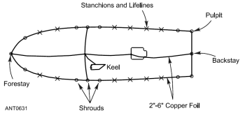 A bonding wire, or better yet a copper strap (it can be very thin!), is connected from bow-to-stern
on each side, connecting the fore-stay, lifeline stanchions, chainplates, bow and stern pulpits and the backstay.
Similarly, on the level of the water line, the metal-based underwater components are connected.
Other bonding wires are run from the bow, stern and chainplates on both sides to a common connection at the base of the mast.
The fore-and-aft bonding can be attached to the engine and to the keel bolts.
A bonding wire, or better yet a copper strap (it can be very thin!), is connected from bow-to-stern
on each side, connecting the fore-stay, lifeline stanchions, chainplates, bow and stern pulpits and the backstay.
Similarly, on the level of the water line, the metal-based underwater components are connected.
Other bonding wires are run from the bow, stern and chainplates on both sides to a common connection at the base of the mast.
The fore-and-aft bonding can be attached to the engine and to the keel bolts.
Since this set up, electrically connects dissimilar metal parts that are also
electrolytically connected through the seawater, special sacrificial anodes
(zinc- or aluminium based) necessarily must be part of this system, in order to prevent galvanic corrosion
on the structural hull-, deck- and rigging components.
The layout suggested above, indicates the use of 6-cm to 20-cm wide copper strap for the connections.
This is required to provide a low impedance grounding but that material may not always be readily available.
It turns out that a series of parallel wires spaced a few cm apart will have an impedance similar
to a wide copper strap and may be easier to install.
If an insulated part of the back-stay is used as HF-antenna, the automatic tuner should be mounted
as close to the back-stay as possible, preferably just under the after deck.
Run copper ground tape from the tuner ground to the stern pulpit/lifelines, to the engine, and to a
keel bolt.
It is good practice to include the HF/SSB radio itself in this network of ground tapes.
 Sintered bronze ground plates (e.g. Dynaplates) can be used as alternative radio grounds in situations
where the ballast or engine is unavailable or awkward to connect.
If the ballast, engine, and lifelines are available, however, they generally make a better high performance
HF-ground.
Sintered bronze ground plates (e.g. Dynaplates) can be used as alternative radio grounds in situations
where the ballast or engine is unavailable or awkward to connect.
If the ballast, engine, and lifelines are available, however, they generally make a better high performance
HF-ground.
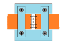
To avoid making another DC ground to the engine via the HF/SSB radio copper
ground strip, a self-made DC-block capacitor can be used.
For this, a 5-mm gap is cut across the copper tape and several 150-nF/100V ceramic
capacitors are soldered across the gap.
If five or more such capacitors are used in parallel, the impedance at 300 kHz is less than 1 Ohm
and even lower for higher frequencies.
The two parts of the separated copper foil should be securely mechanically fixed
(e.g. on a piece of plexiglass) as well as carefully kept clean and dry.
Galvanic Protection
Lightning ground, RF ground and optionally AC ground, all need a direct connection to the seawater.
Lightning ground can be best obtained through a connection of the mast and rigging direct to
the keel ballast.
If required, AC ground is connected to the engine and RF ground can work without any restriction
by providing an AC coupling through a DC-block capacitor to either the keel or the engine block.
This prevents any corrosion relevant DC current occurring from the RF ground and
a galvanic insulator can do the same for AC-power ground.
Generally any thru-hulls or other immersed metal parts should be kept electrically isolated.
Specifically, the keel/ballast, rudder shaft, engine/prop, and all thru-hulls should not be
connected electrically.
This is the best protection against stray current corrosion.
In an increasing number of marinas, there are substantial DC electric currents going through
the water.
If the immersed metal hull parts are bonded, the electric stray current will take the lower resistance
path offered by the boat's grounding system in preference to the surrounding water, and current
will flow into one of the hull metal bits, through the in-board bonding wires, and then out at
another bit of metal.
The bit of metal or thru-hull that has the misfortune to be on the anodic side of the
the bonding system will corrode. Depending on the current rating, sometimes rapidly.
The sacrificial zinc is only intended to protect against the modest galvanic potentials and therefore currents
that are caused by the dissimilar metals that are immersed and electrically connected together on
your own boat. This zinc is incapable of supplying enough galvanic potential to protect against
substantial DC currents that may be flowing in the water.
Without carefully designed ground system, these DC currents in the water will cause electrolytic corrosion
to your bonded thru-hulls or metal parts.
|