Radio Antennae
In a communication system, the antenna is usually the performance determining part.
It will both have to radiate the full transmitter power as well as to pick
up weak signals from distant stations to be of use.
Antennae are frequency selective, and thus if they are made suitable for operation
in a complete frequency band this will always be a compromise between practical use
and performance.
For "Line-of-Sight" communication equipment such as VHF transceivers, maximum range
is obtained through installation of the antenna at the highest possible position
on the vessel. Antenna Principles
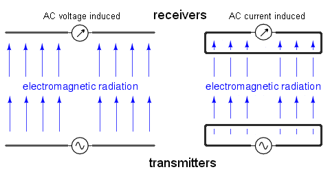
An antenna is a device consisting basically of an electrical wire and designed
to produce a dispersing electromagnetic field.
The electromagnetic radiation is generated by the accelerating and decelerating
motion of oscillating electrons in the electrical antenna wire.
This oscillation is driven by introducing an alternating electrical current in the
antenna structure.
The amount of radiation is proportional to the current fed into the antenna
(more current more oscillating electrons) and high current at low impedance can
favourably be obtained in a resonant system. But the condition of resonance is
not a prerequisite for radiation. Any piece of wire carrying alternating
current will radiate and produce a dispersing electromagnetic wave.
While the dipole looks like a simple open circuit, and the
loop a short circuit, these pieces of wire are effective radiators of
electromagnetic fields when connected to AC sources of the proper frequency.
The two open wires of the dipole act as a sort of capacitor (two conductors
separated by a dielectric), with the electric field open to dispersal
instead of being concentrated between two closely-spaced plates.
The closed wire path of the loop antenna acts like an inductor with a
large air core, again providing ample opportunity for the field to
disperse away from the antenna instead of being concentrated and contained
as in a normal inductor.
Antennas are frequency selective devices, and for optimal
performance the physical dimensions must be matched to the wavelength
(λ = c/f) of the electromagnetic waves they are expected to transmit
or receive.
Optimal electromagnetic radiation is achieved on the resonance
frequency of an antenna. Radiation ResistanceIf power is fed into the antenna, a small fraction will
be dissipated in the resistive part of the antenna structure. The bulk
of the power will usually be radiated in free space and since power
can only be dissipated in a resistance, it is convenient to consider
the radiated power to be dissipated in an imaginary resistance which is called
radiation resistance of the antenna. PolarizationThe polarization of a radiated electromagnetic wave
is determined by the direction of the lines of force making up the
electric field component. If the lines of electric force are parallel
to the surface of the Earth, the wave is said to be horizontally polarized.
If the lines of electric force are orthogonal to the surface of the Earth
the electromagnetic wave is vertically polarized.
In the case of long distance propagation through the ionospheric layers,
atmospheric reflection and refraction may introduce a degree of cross polarization
which results in signals arriving at the receiving antenna with both
horizontal and vertical components present. Since the atmospheric conditions
are constantly changing, also the polarisation components may vary over
short time spans.
This is the main reason why long distance stations are received with a
noticeable fading effect. If the receiving wave happen to be oriented along
the receiver antenna, a maximum signal output is obtained.
But after some time the orientation of the receiving wave may
have rotated over 90 degrees and a minimum antenna output is obtained. The advantage of vertical polarisation (vertical antenna)
is the ability of horizontally omnidirectional communication. This is good for
broadcasting but in case of point to point connections, only a fraction of the
transmitted power will be beamed in the direction of the receiving station.
For all other directions, the transmitter will produce interfering noise.
Moreover, due to the omnidirectional characteristic, a vertical receiver antenna will
receive noise and interfering signals from all directions. The Dipole AntennaThe basic dipole antenna was developed by Heinrich Rudolph Hertz
around 1886. These antennas are the simplest practical antennas from a theoretical
point of view. Typically, a Hertz or dipole antenna is formed by two quarter-wavelength
conductors or elements placed back to back for a total length of one half of a wavelength.
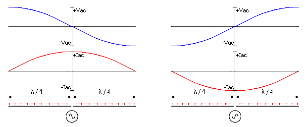
A standing wave on an element of a quarter-wavelength length yields the greatest
voltage differential, as one end of the element is at a node (+Vac) while the other
is at an anti-node (-Vac) of the wave.
The dipole antenna is fed at the (isolated) junction of both quarter-wavelength conductors.
At the resonant frequency, the feed-point impedance of an antenna is low.
This enables to couple energy into the antenna at a low voltage (at the feeding point)
and it can therefore be an efficient radiator.
The current in the dipole elements, is zero at the ends and will swing between the
maximum values (+Iac and -Iac) in the center of the dipole (the feeding point).
Note that the direction of the current (indicated by the red arrows above the dipole)
at a certain instance is the same in both the dipole branches - to the right in both
elements or to the left in both elements.
Clearly, the antenna does not radiate uniformly along the entire length.
At the ends the current (and the acceleration of electrons) is zero and thus the
electromagnetic radiation will also be zero at the ends of the dipole.
A dipole is most commonly fed at the center, where it presents a balanced, 72 Ohm load to the feed line. Notice that as there is a phase shift between current and voltage, the impedance is NOT purely resistive at this point! Although a dipole can be fed anywhere along its length, center fed is the most common, and the easiest because moving the feed point will also change the impedance of the dipole. The following table shows the impedance of an example dipole antenna for some specific lengths around one half of the wavelength. Besides length, the impedance depends also on the antenna diameter and ground plane characteristics:
For a dipole length of 0.48 times the wavelength, the impedance of the
antenna is purely resistive (73 Ohm), whereas for exactly 0.50 times
the wavelength, the load has an inductive component and the total
impedance is approximately 90 Ohm.
Notice however, that only the resistive part of the dipole is
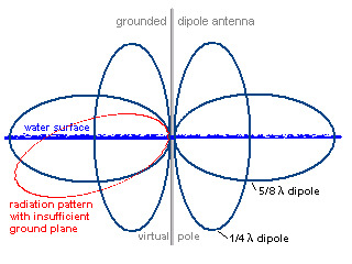
dissipative and relevant for power concerns. Grounded Dipole Antenna
Ground is a good conductor for low- and medium range frequencies and acts as a
large mirror for the radiated radio waves. This results in the ground reflecting
a large amount of energy that is radiated downward from the antenna mounted over
it. Using this effect of ground, an antenna only a quarter wavelength
long can be made to act as a halve-wavelength antenna. The grounded quarter-wavelength antenna has a radiation pattern (directional characteristics) similar to that of a half-wave dipole antenna. It has a feed point impedance over a perfect ground of 36+j*21 ohm (an ungrounded half-wavelength antenna has an impedance of 73+j*43 ohm). Above real ground it is usually between 50 and 75 ohm. This makes a good match for a coaxial (unbalanced) 50-ohm cable with the shield connected to ground. A longer mono-pole antenna can produce even lower radiation
angles than the standard quarter-wavelength antenna, but eventually these antennas
become too large to easily construct and handle.
Moreover, on rolling and pitching yachts a low radiation angle may have an
unfavourable impact on the transmission range.
A length often used for VHF mobile operation is the 5/8th wavelength.
Theoretically, a gain of 3dB can be obtained compared to the grounded
quarter-lambda antenna. This 5/8th wavelength antenna has a higher feed
impedance and requires a matching network to match most feeder cables. Vertical antennas provide an omni-directional pattern in the horizontal plane so they receive and transmit equally well in all directions. This also makes them susceptible to noise and unwanted signals from all directions. Effects of a Finite Size Ground Plane on the Monopole AntennaThe simplest monopole antenna consists of a vertical element with an optimal length λ/4 on the ground plane. The radius and the shape of the ground plane will affect the radiation pattern and input impedance of the monopole antenna (usually r >>λ/4). In practice, monopole antennas are used on finite-sized ground planes. This affects the properties of the monopole antennas, particularly the radiation pattern. The impedance of a monopole antenna is minimally affected by a finite-sized ground plane for ground planes of at least a few wavelengths in size around the monopole. However, the radiation pattern for the monopole antenna is strongly affected by a finite sized ground plane. The resulting radiation pattern radiates in a "skewed" direction, away from the horizontal plane (larger "take-off" angle). Effects of Diameter Size on the Monopole AntennaThe monopole diameter will affect the antenna bandwidth. A larger diameter will result in a larger bandwidth. Gain or Directivity
Ground PlaneThe vertical quarter-wavelength antenna works well only when placed
over a good ground system. Poor ground causes antennae to operate less
efficient. In the radiation pattern the main RF power lobe will be directed towards
the ground plane. It is possible, to lose up to 90% of the RF power by heating
the space under the main radiation lobe, instead of transmitting the energy as
electromagnetic wave. Antennae for VHF transceivers
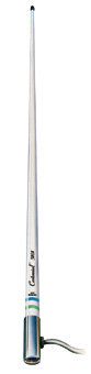
Just as important as the antenna is the cable connecting your VHF radio to the antenna. VHF radios use a special coaxial cable that is really two cables, one inside the other. The central conductor goes to the antenna, while the braided outer conductor (which is insulated from the inner) goes to the ground as well as serving to keep radio energy from escaping between transmitter and antenna. The best type of coax has a stranded copper center conductor, with a high percentage (such as 80 to 90 percent) of copper, while cheaper cables will have a lower amount of copper. Reduced radio performance can be caused by invisible cracks in the coaxial cable, by corrosion in or around the end fittings, by moisture seeping into the cable, or by using a cable, which is too long. The common marine installation uses RG-58 cable for short runs of up to 6 meters. For a longer run, such as to the top of a mast, RG-8 cable can be used. RG-8 is a heavier cable and requires special tools to replace the coax fittings at the ends, but it has lower loss per length. For a little extra money RG-213 cable can be installed, which is a military specification cable that has a minimum signal loss like the RG-8 but with an abrasion and ultraviolet proof jacket for long life. Antennae for HF-SSB transceiversAntennae for MF-HF sets using single-sideband
are physically much larger than those for VHF, but still not as large electrically
as they should be. Vertical whip antennae are 8 meters or more in length
and still must have an antenna tuner box to make up for a lack of physical
length to properly match the transceiver. A further essential element of a SSB installation is a good "ground plane" connection, which is not necessarily needed for a VHF areal (mainly because the reach is limited by line-of-sight distance rather than the transmission characteristics of the antenna). Antenna LengthThe length of the antenna must be considered in two
ways. It has both a physical and an electrical length, and these two
are never the same. The reduced velocity of the radio wave on the antenna
and a capacitive effect knows as "end effect" make the antenna seem electrically
longer than it is physically. The contributing factors for this difference are
the ratio of the diameter of the antenna to its length and the capacitive
effect of terminal construction (insulators, clamps, ...) used to support
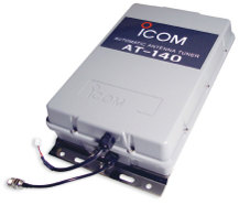
the antenna. length [m] = 1/4 * 300/f * 0.95 with f expressed in MHz Antenna PerformanceFor optimal transmission of the transmitter
HF power to the antenna, the load impedance of the antenna
has to be tuned to the transmitter output impedance.
The transmitter must be electrically matched to the antenna so that the antenna will absorb the transmitter power and radiate it into the atmosphere. This is most often accomplished with a microprocessor controlled automatic antenna coupler or "tuner". The coupler varies the "electrical length" of the vertical radiator wire by switching various capacitors or inductors contained in the coupler into the circuit between the radio and the antenna wire. This allows a wide range of operating frequencies to be served by a fixed length antenna. Some couplers provide a readout of the quality of the "match" achieved between the transmitter and the antenna. This is expressed in terms of standing wave ratio, SWR, a ratio of unity, 1.0, is optimum.
So the high impedance of the antenna must be compensated with an integrated amplifier (impedance transformer) directly at the feeding point of the antenna. Because this feeding point is usually outdoor, the antenna amplifier is usually fed through the antenna coax cable. Antenna Impedance Matching
Impedance matching is important to achieve maximum power transfer between two devices such as
a feed line and an antenna.
A transformer is a passive device that transforms or converts a given impedance,
voltage or current to another desired value.
In addition, it can also provide DC isolation, common mode rejection,
and conversion of balanced impedance to unbalanced or vice versa. n = N1/N2 V2 = n * V1 I2 = I1 / n Z2 = n2 Z1
It shows that the output voltage (V2) is equal to turns ratio (n) times the
input voltage (V1). The output current (I2) is input current (I1) divided by
the turns ratio and the output impedance (Z2) is input impedance (Z1)
multiplied by the square of the turns ratio. | ||||||||||||||||||||||||

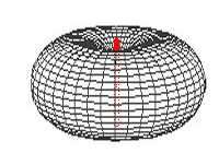 Radiation is maximal in the plane perpendicular to the dipole and zero in the direction
of wires which is the direction of the current. The emission diagram is circular section
torus shaped (right image) with zero inner diameter.
Radiation is maximal in the plane perpendicular to the dipole and zero in the direction
of wires which is the direction of the current. The emission diagram is circular section
torus shaped (right image) with zero inner diameter.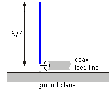 For a given wavelength the Marconi antenna is the smallest antenna
with reasonable efficiency and so is a popular choice for mobile communication.
It can be thought of half of a dipole with the other half appearing as a virtual
image in the ground.
The current in the reflected image has the same direction and phase as the
current in the real antenna. Although the quarter-wavelength conductor and its image
together form a half-wave dipole it radiates only in the upper half of space.
For the 156 MHz marine VHF band with wavelengths of about 2m, a typical
Marconi antenna is only 0.5m long.
For a given wavelength the Marconi antenna is the smallest antenna
with reasonable efficiency and so is a popular choice for mobile communication.
It can be thought of half of a dipole with the other half appearing as a virtual
image in the ground.
The current in the reflected image has the same direction and phase as the
current in the real antenna. Although the quarter-wavelength conductor and its image
together form a half-wave dipole it radiates only in the upper half of space.
For the 156 MHz marine VHF band with wavelengths of about 2m, a typical
Marconi antenna is only 0.5m long.
 Antennae can normally not be mechanically (length) tuned to the
transmission frequency.
But they can be electrically tuned with a "matchbox".
A matchbox is an electrical device including a bank of switchable
impedances.
The matchbox is installed directly at the feeding point of
the antenna and is usually controlled electrically from the
transmitter.
The tuning must be performed each time the transmission frequency
is changed.
The tuning can be initiated manually or automatically by the transmitter.
Antennae can normally not be mechanically (length) tuned to the
transmission frequency.
But they can be electrically tuned with a "matchbox".
A matchbox is an electrical device including a bank of switchable
impedances.
The matchbox is installed directly at the feeding point of
the antenna and is usually controlled electrically from the
transmitter.
The tuning must be performed each time the transmission frequency
is changed.
The tuning can be initiated manually or automatically by the transmitter.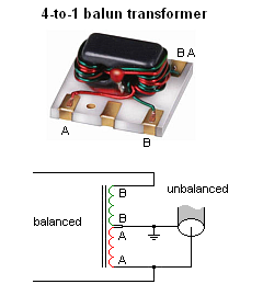
| Cover << Sail Away << Marine Radio Communication << . | . >> Transmission Lines | last updated: 24-Jul-2013 |